Bringing Up a 0.39-Inch 1024x768 Micro OLED: Wiring, Init Order and First Light in an EVF
Getting a 0.39-inch 1024x768 Micro OLED to show a stable frame is less about writing clever code than about order of operations: rails first, reset timing second, the register table third, pixels last. The panel is small, emissive and specified at a 10,000:1 contrast ratio with 345 cd/m2 maximum brightness, which means a black frame is genuinely black and a mistake in the init sequence shows up immediately as a blank or washed-out image instead of hiding behind a backlight. In a camera electronic viewfinder the module is also the last element in an optical path, so bring-up has to cover signal integrity, frame pacing and thermal behaviour rather than just a picture on the bench. What follows is the host-side preparation, a bring-up order that reaches first light predictably, and the checks that decide whether the prototype is a demo or a viewfinder you can put in front of a user's eye.
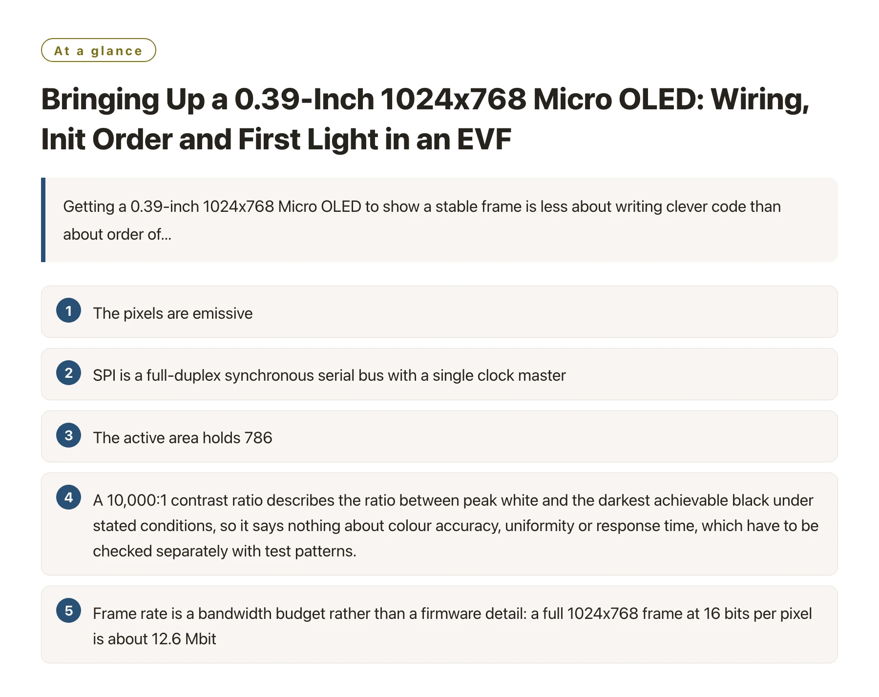
Key takeaways
- The pixels are emissive, so there is no backlight to sequence and no lamp warm-up; a dark screen at first light almost always means the reset pulse, the SPI mode or the register table is wrong rather than a dead panel. [1]
- SPI is a full-duplex synchronous serial bus with a single clock master, so the panel's clock, data and chip-select timing all come from the host, and a clock phase or polarity mismatch delivers bytes the panel parses as meaningless. [2]
- The active area holds 786,432 pixels, and because panel size is quoted on the diagonal the arithmetic works out to roughly 3,300 pixels per inch - far beyond what the eye resolves on a desk monitor, which is exactly why a bare panel acts as a magnifier for every wiring and timing defect. [3]
- A 10,000:1 contrast ratio describes the ratio between peak white and the darkest achievable black under stated conditions, so it says nothing about colour accuracy, uniformity or response time, which have to be checked separately with test patterns.
- Frame rate is a bandwidth budget rather than a firmware detail: a full 1024x768 frame at 16 bits per pixel is about 12.6 Mbit, so most viewfinder designs carry live video over the module's RGB path and keep the serial interface for configuration and stills.
Bring-up order matters more on a Micro OLED than on a large TFT, because there is no backlight assembly to mask a partial failure. When the panel stays dark you cannot tell from the outside whether the host is not clocking, the reset pulse is too short, or the register table never arrived. The only reliable method is to fix one variable at a time and observe the result at each step.
The part in question is a 0.39-inch 1024x768 active-matrix Micro OLED with an RGB/SPI interface, a 10,000:1 contrast ratio and 345 cd/m2 maximum brightness, positioned by the vendor for AR/VR, medical imaging and industrial equipment as well as camera viewfinders. For a camera electronic viewfinder the interesting consequences are that the image is emissive, that the whole optical stack fits in a few cubic centimetres, and that the host must sustain a video-rate stream rather than an occasional still image.
The sections below cover what the host board has to supply, a bring-up sequence that reaches first light without guesswork, the init-sequence decisions that are easy to get wrong, and the viewfinder-specific checks on optics, heat and frame pacing. Modules in this class are normally delivered as a bare panel on a flex with a register-level interface, which is why the host-side details tend to dominate the integration schedule.
What the host board must supply before the panel does anything
A module in this class arrives as a glass panel on a flex with the interface signals broken out and little else. There is no controller board, no level shifter and no supply sequencer in the box, so the first-light checklist starts with the rails named in the panel datasheet. Take both the values and the required order from that document rather than from a forum thread or a similar-looking panel, because the sequencing tolerance on a small emissive panel is tighter than the absolute voltage values suggest.
Two wiring details cause most first-light failures. The first is the reset and chip-select lines: if they float while the host boots, the panel can latch a partial command before your driver takes control, so they need defined pull resistors and a host pin that is driven early. The second is logic level, because the interface may run at a lower voltage than the host; a 5 V board needs translation on every signal including the clock, since a clock that swings above the panel's own supply is a reliability problem rather than a timing curiosity.
Modules such as the 0.39-inch 1024x768 Micro OLED from DisplayModule display modules are representative of how these parts are documented: resolution, interface, contrast and brightness are published up front, while the electrical detail lives in a timing table that the driver has to implement exactly.
Sequence the rails, then hold reset
Power sequencing exists because internal charge pumps and bias circuits have a preferred order; applying a rail out of turn can forward-bias a junction that was never meant to conduct. Follow the datasheet order, hold the panel in reset while the rails settle, and release reset only after the host clock is running and stable.
Keep the flex short and the ground return solid
On a first prototype the serial clock is often routed over a jumper wire, which is tolerable at low clock rates and marginal at high ones. Keep the flex and any adapter short, return ground alongside the clock, and add a small series resistor at the source if the edges ring. An image that appears only when you touch the ribbon cable is a signal-integrity problem, not a firmware problem.
Write the rail order and the reset timing into the schematic notes, because the next engineer will otherwise rediscover them with a dark panel.
A bring-up order that reaches first light without guesswork
- Verify the rails with the panel disconnected. Bring the host board up alone, confirm each rail arrives in the intended order at the intended value, and check the idle level of the reset line. Ten minutes here is cheaper than one panel.
- Prove the serial link while the panel is held in reset. Use a logic analyser to confirm mode, bit order and chip-select framing against the datasheet, or at minimum run a host-peripheral loopback test to validate the clock divider and the transmit path.
- Release reset and send the vendor init table unchanged. Write the register list exactly as supplied before editing anything. Panels of this class rely on power and timing registers that the table sets; hand-tuning one entry first is the quickest route back to a blank screen.
- Set the address window, then push one solid colour. Define the column and row window, select the pixel format the host is actually sending, and fill the screen with a single value. A uniform field separates interface faults from image-pipeline faults.
- Move to a gradient and a line pattern. Banding, channel swaps and inversion appear on a gradient far earlier than in a photograph, while a one-pixel checkerboard exposes column and row driver defects that a flat fill hides completely.
- Close the loop with live video last. Introduce real frames only once the static path is known good, so that any tearing or flicker you then see belongs to frame pacing rather than to bring-up.
Choosing the host board for a first-light run
| Host class | Where the pixel stream comes from | Strength for bring-up | Constraint to plan around |
|---|---|---|---|
| Arduino-class 8-bit MCU | Hardware or bit-banged serial output from a small frame buffer in RAM | Simplest wiring and a very readable driver, excellent for proving timing and the init table | RAM and clock ceiling: full-frame buffers and video-rate updates are out of reach |
| ESP32-class SoC | Hardware serial peripheral with DMA, fed from a partial frame buffer | Good middle ground with fast clocks, enough RAM for a windowed update and wireless debugging | Background tasks and shared buses can steal DMA bandwidth, so isolate the display transaction |
| STM32-class MCU | Dedicated serial peripheral plus a parallel RGB path on larger parts | Predictable timing and low jitter, which matters when the pixel stream must never stall | Pin count and alternate-function mapping have to be planned before the PCB is drawn |
| Raspberry Pi / Linux SBC | Serial writes from user space or a kernel driver, with a GPU pipeline upstream | Fastest route to moving images and the easiest place to script test patterns | Scheduling jitter: user-space writes are not deterministic, so frame pacing needs explicit care |
The init table is a contract, not a starting point
Every small OLED panel of this type powers up in an undefined state and depends on a register list supplied by the panel or module vendor. That list configures the internal power circuits, the timing generator and the gamma behaviour, and on a 1024x768 part it also selects how many bits per pixel the interface expects. Write it byte for byte on the first pass, then diff against it whenever an image looks wrong, because an unnoticed edit is indistinguishable from a hardware fault.
The two most common image-level mistakes at this stage are a pixel-format mismatch and an unset address window. If the host sends 16 bits per pixel while the panel expects 18 or 24, colours shift and gradients posterise; if the window is left at its power-on value, the frame lands in the wrong part of the active area or wraps around the edge. Neither fault produces an obviously broken picture, which is why both survive into later prototypes and get blamed on the optics.
Gamma is the related trap. Because the panel is emissive and driven in the analogue domain, the mapping from code value to emitted luminance is not linear, and a table written for one panel family rarely transfers cleanly to another. Change one entry at a time and re-measure against a fixed test pattern, otherwise you end up tuning two errors against each other and calling the result calibrated.
Record every deviation from the vendor table in the driver source with a date and a reason, so the next person can tell a deliberate change from an accident.
What a camera viewfinder adds on top of first light
In an electronic viewfinder the panel is not a status display; it is the optical source the user looks at, so a stable image on the bench is only half the job. The 345 cd/m2 maximum brightness and 10,000:1 contrast ratio describe the panel's own output, and because the pixels emit rather than modulate a backlight, black is produced by switching emitters off. That is what makes a dark scene look dark instead of grey, and it is also why brightness is the scarce resource: any protective window or diffuser added in front of the panel spends it.
Contrast ratio has a precise meaning worth keeping straight. It is the ratio between the luminance of the brightest white the display can produce and the luminance of its darkest black, measured under the same stated conditions. [4] A ratio quoted without measurement conditions characterises the panel family rather than your viewfinder, and ambient light reflected from a cover glass can reduce perceived contrast long before the panel's own ratio becomes the limiting factor.
Heat is the second viewfinder-specific concern. The module is small and sits close to the user's face, so even modest dissipation raises the local temperature, and a panel whose brightness drifts as it warms will slowly change the image the photographer is using to judge exposure. Give the panel a thermal path to the housing, keep the flex away from hot components, and characterise brightness over ten minutes of continuous operation rather than at the instant of power-on.
Frame pacing is the third. Full frames over a serial bus are bit-limited: 1024x768 at 16 bits per pixel is roughly 12.6 Mbit per image, so a 20 MHz serial clock delivers fewer than two complete frames per second even before protocol overhead. The module pairs its serial interface with an RGB path for exactly this reason, and the module's power-saving behaviour is worth using deliberately - dimming or refreshing only the changed window keeps a continuously running viewfinder within the thermal and power envelope it was designed for.
An EVF is finished, not when the first frame appears, but when the image stays stable while the host runs its real workload, the enclosure is warm, and the user is looking through the cover glass.
Keep a known-good reference build and a photograph of the wiring. When a change breaks the image you need something you can flash in ten seconds to prove whether the fault is hardware or firmware; without it, every debugging session starts by re-litigating the init table. Tag the build, note the register list revision, and keep the two together.
Sources
Frequently asked questions
Why does a 0.39-inch Micro OLED stay black after the init table has been sent?
The three usual causes are a reset pulse that is too short or released before the host clock is stable, a serial mode mismatch that leaves the panel parsing shifted bytes, and an address window that was never set, so pixels are written outside the visible area. Confirm clock and chip-select framing with a logic analyser first, then re-send the vendor table unchanged and retest before changing any register.
Do I need a level shifter to drive this module from a 5 V board?
It depends on the interface voltage the panel datasheet specifies, and that document is the authority rather than the convenience of the host board. If the panel's logic supply is lower than the host's input and output levels, every signal including the clock needs translation, because a clock swinging above the panel's own supply can stress the interface even when the data lines appear to work.
Can I stream viewfinder video over the serial interface alone?
Only at low frame rates. A full 1024x768 frame at 16 bits per pixel is roughly 12.6 Mbit, so even a fast serial clock leaves a few frames per second once protocol and command overhead are counted. Camera viewfinders normally carry live video over the module's RGB path and reserve the serial link for configuration, test patterns and still images.
What should I measure once the first image appears?
Measure the quantities that decide whether the design is shippable: brightness at the centre and at the corners, the panel temperature after ten minutes of continuous operation, and image stability while the host runs its real workload rather than a test loop. Also check the black level with the cover glass fitted, because reflected ambient light is what usually spoils perceived contrast in a viewfinder.